|
JET Energy, Inc.
|
Working for Safe and Efficient
Heat Products to Serve You
|
Introduction to Lattice Assisted
Nuclear Reacdtions
-
Drs. Martin Fleischmann and Stanley Pons initially underemphasized the
fact that the cold fusion reactions involve materials which are very difficult
to prepare. This introduction is a scientific background which will
discuss cold fusion, and some of the science involved. This information,
like the reasons why the reactions are difficult to obtain, has become
clearer only after understanding and control of the physics, material
science and engineering was worked out. References are provided below.
-
Since the announcement of the discovery of cold fusion in March 1989, laboratories
in over 30 countries have investigated the cold fusion phenomena.
Nonetheless, scientists and researchers in this field field,
the science and engineering of loading isotopic fuels (such as hydrogen)
into a material (such as palladium) have been facing a difficult struggle
involving metallurgy, electrochemistry, and nuclear and solid-state physics.
-
JET Energy, Inc. has significantly contributed to the development
of the evolving landscape of cold fusion -- and its utilization, by developing
a continuum electrophysics model which has led to codeposition, the optimal
operating point, and Phusor technology, and by developing a series of devices
which has led to the MIT ICCF-10 Cold Fusion
Demonstration. We have sought not only the better performance,
improved understanding and control of the physics, better and more diverse
materials, and advanced engineering, but also quality assurance
and quality control. By tackling this advancing science with these
new ideas, we have moved closer to maximizing the rate of the desired safe
heat producing reactions.
 COLD
FUSION BACKGROUND: Cold fusion times,
ISSN #1072-2874
Swartz. M., "Patterns of Success in Research Involving
Low-Energy Nuclear Reactions", Infinite Energy, 31, 46-48, (2000).
MECHANISMS OF HEAT PRODUCTION
USING CONVENTIONAL PHYSICS and IMPROVED ENGINEERING
Cold fusion is the generation of, what was initially thought to be "anomalous",
'excess' heat at low temperatures. As Dr. Melvin Miles (China Lake, US
Navy; COLD FUSION TIMES issue #V1-2) and others have demonstrated,
helium, used to fill ordinary lighter-than-air balloons, is the product
generated by the cold fusion reactions, if adequate loading
and other engineering factors have been achieved (COLD FUSION TIMES
issues #V2-1, 3-1, 4-1).
The helium is generated by, and linked to, the production of excess heat.
This helium is beyond the amount which can leak in from the ambient environment
when metal flasks are used to isolate the reactions from the environment.
This generation of energy -- with a safe product for a change -- is therefore
quite important.
As Dr. Swartz explained in the "21Century Broadcast" with Dr.
Mallove:
"What the cold fusion reactions appear to be are the generation of helium
from heavy hydrogen loaded into palladium. This generates tiny microscopic
amounts, incredibly small amounts, of helium, but because E = mc2 we get
a lot of energy out. The amount of new energy is substantial, and
is often on the order of the energy that we put in. As a result,
what we see, and what can be measured, is not only the dissipated heat
of what we put in but also the added energy from these additional nuclear
reactions [that are totally safe because they do not generate either neutron
or additional penetrating ionizing radiation]. And the sum of the
two energies are such that we see a new energy which is greater than what
we put in. And the difference is what we call 'excess energy'."
|
MATERIAL DEVELOPMENTS
-
Cold fusion technology has developed using several materials which now
include palladium, titanium, nickel, and other metals in a variety of configurations.
Early on, considerable focused upon the use of alloys, additives, and other
techniques (e.g. COLD FUSION TIMES issues #V1-3, 3-2, 4-2,
etc.). Preparation of the proper loaded, prepared, and poised materials
has led to higher power levels and recognition of the product - helium.
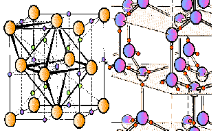
|
| In the figure on the right, the heavy water is composed
of D2O molecules and is used to electrochemically
load the palladium. The metallic palladium is on the left hand side
of the figure, and is shown fully loaded. |
|
COLD FUSION IS FIRST DRIVEN BY LOADING APPROPRIATELY PREPARED MATERIALS
The cold fusion reactions follow after successful loading of the metals
by an isotope of hydrogen (protium or deuterium).
|
QUASI-ONE-DIMENSIONAL (Q1D) MODEL OF LOADING
This continuum electrophysics model has successfully led to
understanding of loading, device failure, codeposition, the optimal operating
point, and Phusor technology. The equations enabled production of
a series of devices robust enough for the MIT
ICCF-10 Cold Fusion Demonstration.
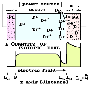
|
| The figure [after Swartz, Fusion Technology, 296-300 (1992)] qualitatively
shows the loading of the material (palladium) with the inhomogeneous distribution
of isotope (deuterium obtained from heavy water) . |
-
The applied electric field intensity produces migration in the electrolyte
and loading of the metal.
-
Q1D models have successfully predicted that the loading of hydrogen isotopes
into the metal is an effect which is actually opposite the generation
of bubbles which are classically associated with electrolysis.
-
Another, important result is that If insufficient voltage is used, or if
the metal is defective (like a balloon with a moderate leak) it may simply
never adequately fill.
-
Another important result is codeposition which generates excess heat more
quickly.
|
 QUASI-ONE-DIMENSIONAL
(Q1D) MODEL BACKGROUND
Swartz, M, "Quasi-One-Dimensional Model of Electrochemical
Loading of Isotopic Fuel into a Metal", Fusion Technology, 22, 2, 296-300
(1992).
Swartz, M., "Isotopic Fuel Loading Coupled to Reactions
at an Electrode", Fusion Technology, 26, 4T, 74-77 (1994)
Swartz, M., "Isotopic Fuel Loading Coupled to Reactions
at an Electrode", 4, Proceedings: 'Fourth International Conference on Cold
Fusion", sponsored by EPRI and the Office of Naval Research, December
(1993).
Swartz, M., "Codeposition of Palladium and Deuterium",
Fusion Technology, 32, 126-130 (1997).
Swartz, M., "Generalized Isotopic fuel Loading Equations",
"Cold fusion Source book, International Symposium on Cold Fusion and Advanced
Energy systems", Ed. Hal Fox, Minsk, Belarus, May (1994).
NOISE MEASUREMENT, USE OF CONTROLS,
AND THERMAL SPECTROSCOPY
PERMIT IMPROVED SAMPLE INVESTIGATIONS
PALLADIUM SYSTEMS
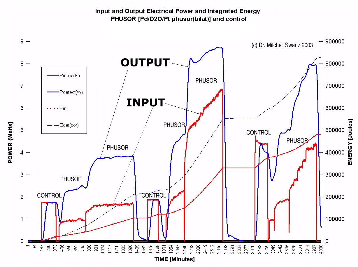
nput electrical power and observed output heat power
(and energies) as a function of time
for the Phusor system and the electrical control
This figure shows the output of a moderate performance cold fusion system.
The figure is a graph which has four curve.The graph shows the input electrical
power and observed output heat power as a function of time over several
days, both for the heavy water deuteron-loaded system and for the electrical
control. Also shown, are the integrated input energy and integrated
energy output of both the cold fusion device and the control, over
several days.
-
It should be noted that the observed output power is much greater for the
deuterium-loaded system as compared to the thermal (joule) controls. There
are two additional energy curves in the figure that corroborate the excess
heat of the deuterium-loaded palladium system compared to the control.
The figure shows the integrated energy curves.
-
The figure shows that in this run, there was an excess heat developed of
more than 300,000 joules compared to the control.
NICKEL SYSTEMS
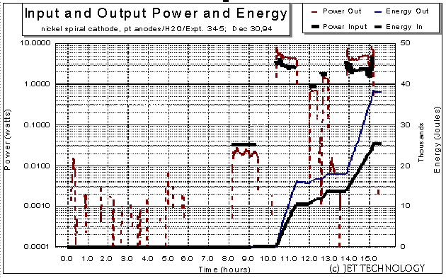
The figure above shows the input and output power (and energy)
of a JET Energy, Inc. Nickel Phusor. This thermal spectrogram
presents the input and output power along with energies of a platinum foil
electrode (4 cm2 area) and a spiral nickel cathode (4.8 cm2
area,
0.059 cm3 volume) -- in ordinary light water. The graph
results the power and energy of two JET Energy Technology generators, compared
with three ohmic (Joule, or thermal) control pulses. The two solid lower
lines are energy curves (input and output). They should be read off the
right y-axis. The remainder of the curves are power curves and are read
on the logarithmic left y-axis. The lower left shows the background
noise and settling time of the experiment which characterizes the system.
 DEVICE
BACKGROUND
Swartz. M., "Consistency of the Biphasic Nature of Excess
Enthalpy in Solid State Anomalous Phenomena with the Quasi-1-Dimensional
Model of Isotope Loading into a Material", Fusion Technology, 31,
63-74 (1997)
Swartz. M., G. Verner, "Excess Heat from Low Electrical
Conductivity Heavy Water Spiral-Wound Pd/D2O/Pt and Pd/D2O-PdCl2/Pt Devices",
ICCF-10 (Camb. MA), Proceedings of ICCF-10, (2003).
Swartz, M, "Improved Electrolytic Reactor Performance
Using p-Notch System Operation and Gold Anodes",
Transactions of the American Nuclear Association, Nashville, Tenn 1998
Meeting, (ISSN:0003-018X publisher LaGrange, Ill) 78, 84-85, (1998).
Swartz, M., "Biphasic Behavior in Thermal Electrolytic
Generators Using Nickel Cathodes", IECEC Proceedings, paper #97009
(1997).
OPTIMAL OPERATING POINTS
SOME EARLY PROBLEMS
WERE OPTIMAL OPERATING POINT RELATED
-
In 1997, Dr. Mitchell Swartz reported that electrodes had to be driven
at a precise in the input electrical power phase space for efficient operation,
and that by considering such, different samples could be evaluated with
respect to each other. This is optimal operating point of each system.
Comprehending the "Optimal Operating Point"--the site at which the reaction
is best operated--around which each device is designed and carefully constructed
has been one major key to understanding and developing cold fusion.
We have learned that the reactions occur only after successful loading
of an active metal by an isotope of hydrogen (reactions to the left of
the peak), and that excessive input of electrical power is wasteful (reactions
to the right of the peak).
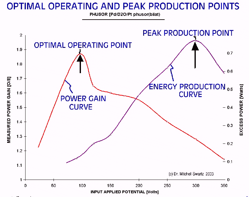
Optimal Operating Point and Peak Production Point
In a Pd/D2O/Pt Phusor System
The figure above shows power gain and the energy production curves for
a JET Palladium Phusor as a function of applied voltage across the device.
As Dr. Swartz has demonstrated in several cold fusion systems, an
optimal operating point can be seen. This narrow peak (maximum) of
the power gain and production curve for the products is observed for the
desired reactions (heat and trace amounts of helium-4) as a function of
input electrical power. Driving with electrical input power beyond
the optimal operating point does not improve the production of the desired
product or power gain, but instead yields a less than desirable falloff
of the production rate and power gain with increasing input power.
 The failure to operate
similar systems near the optimal operating point may account for some of
the widespread difficulties in observing the desired reactions.
 OPTIMAL OPERATING POINT BACKGROUND
Swartz. M., "Control of Low Energy Nuclear Systems through
Loading and Optimal Operating Points", ANS/ 2000 International Winter Meeting,
Nov. 12-17, 2000, Washington, D.C. (2000)
Swartz. M., G. Verner, A. Frank, H. Fox "Importance of
Non-dimensional Numbers and Optimal Operating Points in Cold Fusion", Journal
of New Energy, 4, 2, 215-217 (1999)
Swartz, M., "Generality of Optimal Operating Point Behavior
in Low Energy Nuclear Systems", Journal of New Energy, 4, 2, 218-228 (1999)
Swartz, M, "Optimal Operating Point Characteristics of
Nickel Light Water Experiments", Proceedings of ICCF-7, (1998).
Swartz, M, "Comparative p-notch
[Optimal Operating Point] Characteristics of Solid State Nuclear Systems,
Infinite Energy, 20, 69, (1998)
--- END of Part I --- (c) JET Energy, Inc. 2011 All Rights Reserved
 JET Energy, Inc.
P.O. Box 81135
Wellesley Hills, MA USA 02481-0001
COLD FUSION BACKGROUND: Cold fusion times, ISSN #1072-2874

![]() QUASI-ONE-DIMENSIONAL
(Q1D) MODEL BACKGROUND
QUASI-ONE-DIMENSIONAL
(Q1D) MODEL BACKGROUND


OPTIMAL OPERATING POINT BACKGROUND
 JET Energy, Inc.